Overview of the OSI Model
For Host-to-Host communications to to take place a consistent model is required especially when the Host-to-Host communications is taking place between different vendors. The OSI model was created so different vendors would have a standard way to get data from application to the physical wire.
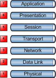
The OSI model consists of seven layers or steps that data should go though while getting from an application to the physical wire.
Understanding the OSI model is vital when dealing with network equipment and in networking in general, understanding the OSI Model will help you to understand encapsulation and many other key network functions much clearer.
Here is what the layers look like;

A good what to remember the seven layers is All People Seem To Need Data Processing.
Here is what each of the layers do;
Application
The application layer is not referring to an application such as a spreadsheet application or a image editing application the application layer refers more to the protocols that sit behind those applications such as SMTP, POP, SNMP, FTP, HTTP etc.
Presentation
The presentation layer works to transform data into the form that the application layer can accept and vice-versa.
Compression and encryption also take place at this layer.
Session
The session layer establishes, manages and terminates connections between applications.
NetBIOS and RPC operate at this layer.
Transport
The transport layer ensures the data transmission is reliable by providing end-to-end error recovery, the transport layer also provides flow control meaning that the Transport layer looks to see if data is coming from more than one application, if so it integrates each application’s data into a single stream for the lower layers.
TCP and UDP operate at this layer.
Network
The Network Layer provides logical addressing, looks after routing and path selection.
Routers, Multi Layer Switches and IP operate at this Layer.
Data Link
The Data Link layer deals with how the data if formatted (Frames), the data link layer also commonly adds error detection and correction by the use of a CRC bit.
Layer 2 Switches, Ethernet, Token Ring are some types of devices that operate at Layer 2.
Physical
The physical layer deals with hardware, it is responsible for activation, deactivating and maintaining the physical connectivity between the two hosts. This physical connectivity could be an electrical single travelling over a copper wire, or it could be pulses of light sent though a fibre optical cable among other things.
Hubs and Repeaters are a Layer 1 device as they have no intelligence each interface is simply physically connected to every other interface.
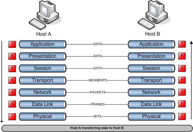
Host-to-Host Communication
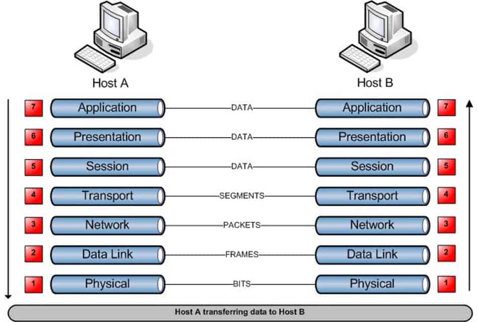
When data is transmitted from one Host (Host A) to another Host (Host B) the data flows down the 7 Layers at Host A and across the physical media in the form of binary data, when it arrives at Host B the data travels back up through the seven layers on Host B.

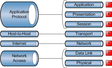
TCP/IP stack vs. the OSI Model
When TCP/IP was created by the Department of Defence around the same time the OSI model was created the TCP/IP operations where defined in its own 4 Layer model.
Each of the DoD layers corresponds to one or more of the OSI layers.


I prefer “Please Do Not Throw Sausage Pizza Away”
Nice Site buddy
Always a good one.
I can’t believe I wrote this post over 10 years ago, check out those classic Visio stencils 🙂